
Accurate gas analysis depends on far more than the analyser itself. Before any measurement takes place, a representative sample of the process gas must be extracted, conditioned, and delivered to the instrument in a controlled, reliable way.
This is the sampling system — and it is one of the most overlooked aspects of gas measurement design. When sampling systems are poorly designed or maintained, the resulting data is unreliable regardless of how sophisticated the analyser is.
This guide covers the key elements of gas sampling system design: what they are, why they matter, and the common mistakes that undermine measurement integrity. It is intended for process engineers, instrumentation engineers, and anyone responsible for the performance of a gas measurement system.
💡 Key principle: Accurate gas analysis requires a representative sample. Every element of the sampling system — from the extraction probe to the analyser inlet — must preserve the composition and integrity of the process gas. If any stage fails, the data fails.
1. Why Sample Conditioning Is Critical
Many engineers focus their specification effort on the analyser: sensitivity, range, response time, certification. These are important. But the best analyser in the world will produce unreliable data if it is receiving a sample that does not accurately represent the process gas.
Sample conditioning failures are responsible for a significant proportion of real-world measurement problems. Common issues include:
- Moisture condensation in sample lines, causing VOC or other soluble species to be absorbed before reaching the analyser
- Particulate contamination blocking filters, restricting flow, or contaminating the detector
- Sample dilution from leaks in the system
- Incorrect sample temperature causing phase changes or condensation
- Pressure fluctuations affecting flow rate and sample representativeness
The consequences can range from measurement drift and poor repeatability to outright data loss — and in compliance-critical applications, incorrect data can have serious regulatory and operational implications.
A well-designed sampling system eliminates these risks by controlling temperature, pressure, flow, and filtration from the extraction point to the analyser inlet.
2. Extraction Probe and Sample Point Selection
The extraction probe is the first element in the measurement chain. Its design and location have a direct impact on the representativeness of the sample.
Probe location
The extraction point should be selected to provide a sample that is representative of the overall process stream. Key considerations include:
- Avoid areas of turbulence, recirculation, or stratification where gas composition may not be uniform
- For stack or duct applications, follow guidance on the number of measurement points relative to duct diameter and flow conditions
- Locate the probe away from dilution air entries, junctions, or other points that could skew local composition
- Consider accessibility for maintenance, calibration checks, and probe replacement
Probe material
The probe must be chemically compatible with the process gas and able to withstand the operating temperature and pressure. For high-temperature applications such as combustion stacks:
- Stainless steel probes are common for general industrial use
- Ceramic-lined or PTFE-lined probes may be required where corrosive gases are present
- Probe length should extend sufficiently into the duct to avoid sampling boundary layer effects near the wall
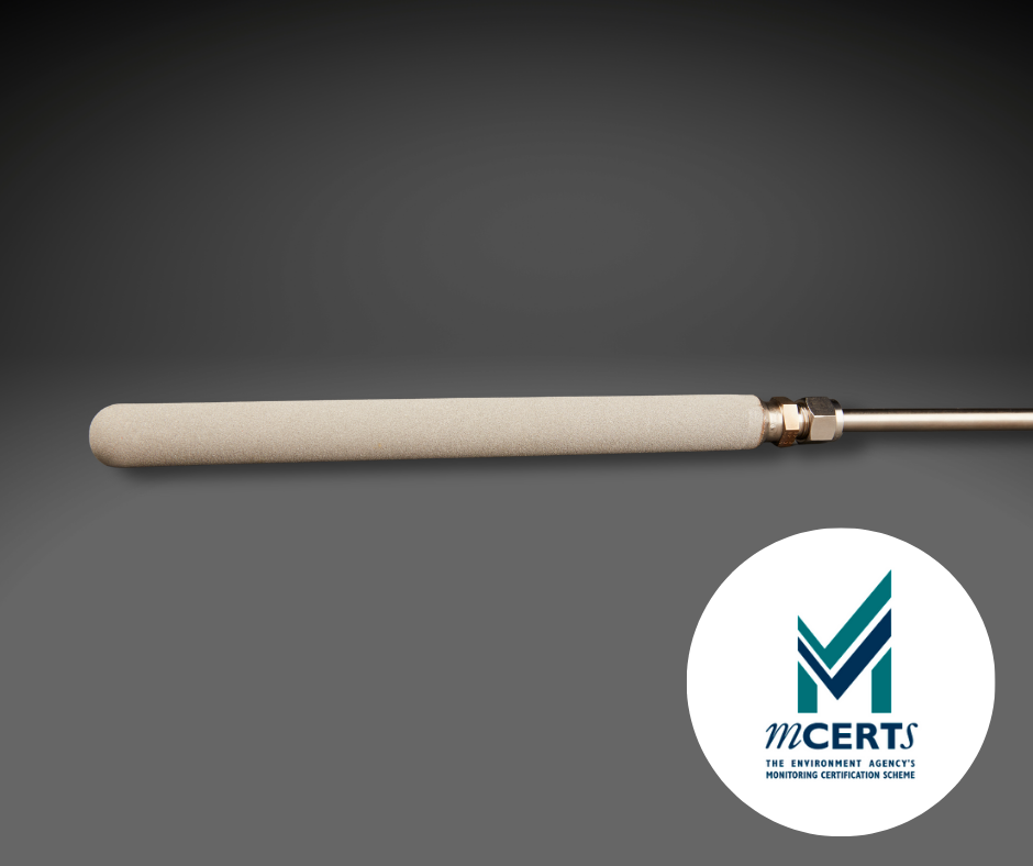
Heated probes
Where the process gas contains condensable components — including water vapour or heavy hydrocarbons — a heated probe prevents condensation at the extraction point. Heating the probe ensures the sample enters the line at a temperature above its dew point, preserving composition from the outset.
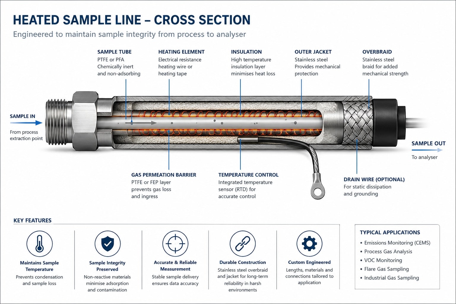
3. Heated Sample Line Design
The sample line carries the extracted gas from the probe to the analyser. In most applications involving VOCs, Total Hydrocarbons, or other condensable species, the sample line must be heated throughout its entire length.
Why heating matters
If the sample gas cools below its dew point at any point in the line, condensation occurs. For VOC measurements in particular, this is a critical failure mode: many organic compounds are partially soluble in water, and dissolved or adsorbed species will not be detected. The measured concentration will be lower than the true value — and the measurement system will be providing false reassurance.
This is not a subtle effect. Significant fractions of the target analyte can be lost to condensation in an unheated or inadequately heated sample line. For compliance monitoring applications, where the integrity of the data is subject to regulatory scrutiny, this is unacceptable.
💡 Real-world example: At ProAmpac Advanced Coatings in Wrexham, Signal Group supplied a heated sample line alongside the MCERTS SOLAR CEMNEX analyser for post-combustion VOC monitoring from their Regenerative Thermal Oxidiser. The heated line ensures the sample remains representative as it travels from the RTO exhaust stack to the analyser — protecting the integrity of the measurement at every step.
Design requirements
A properly designed heated sample line should:
- Maintain a temperature above the dew point of the sample gas throughout its entire length — including at connectors, fittings, and any bends
- Be constructed from materials that are chemically inert to the sample gas (PTFE inner lining is common for VOC and corrosive gas applications)
- Include temperature monitoring to confirm the line is operating correctly
- Be insulated to minimise heat loss, particularly over longer runs
- Be designed with minimal dead volume to maintain fast response time
Temperature selection
The operating temperature of the heated line is determined by the dew point of the sample gas. For combustion applications — including post-RTO and exhaust stack monitoring — Signal’s standard heated line operates at 191°C, well above the dew point of both water and common hydrocarbon species. A lower temperature of 120°C may be used in simpler ambient or low-moisture VOC applications, but for most industrial combustion monitoring this is insufficient. For heavier hydrocarbon streams with very high dew points, even higher temperatures may be required.
Monitoring and alarms
The heated sample line should be fitted with a temperature monitoring system that can raise an alarm if the line temperature falls outside its operating range. A line temperature failure is a data quality event: any measurements taken while the line is cold should be flagged and may be subject to disregard under quality assurance procedures.
4. Sample Filtration
Particulate contamination is one of the most common causes of analyser failure and measurement error. Dust, droplets, and aerosols carried in the process gas must be removed before the sample reaches the detector.
Coarse filtration at the probe
A sintered or ceramic filter at the probe tip provides the first stage of particulate removal. This protects the sample line and downstream components from gross contamination. The filter should be sized and specified based on the expected particulate loading in the process stream.
Fine filtration before the analyser
A secondary, fine-mesh filter — typically located immediately before the analyser inlet — provides the final stage of protection. This filter removes any remaining fine particles and protects sensitive detector components from contamination.
Filter maintenance
Filters require regular inspection and replacement as part of the system maintenance schedule. A blocked or partially blocked filter will:
- Restrict sample flow, causing response time to increase and potentially starving the detector
- Create a pressure drop that can affect the sample composition
- If not replaced, eventually cause a complete loss of sample flow
A good practice is to monitor the flow rate through the system: a gradual decline in flow rate between calibrations is often the first indicator of filter restriction.
5. Condensate Management
Even with a heated sample line, some applications require active condensate management — particularly where the process gas contains very high moisture levels, or where the analyser operates on a dry basis.
Condensate traps
A condensate trap collects liquid that drops out of the sample gas as it cools. The trap must be regularly drained to prevent liquid carry-over to the analyser. In automated systems, condensate traps can be fitted with automatic drain valves on a timed cycle.
Chillers and Peltier coolers
For applications requiring consistent moisture removal to a defined dew point, a Peltier-cooled sample conditioner can be used. This actively cools the sample to a controlled temperature (typically 2–5°C), condensing and removing moisture before the sample is delivered to the analyser. The use of a chiller introduces a correction factor that must be accounted for in the measurement.
6. Flow and Pressure Control
The analyser requires a stable, controlled sample flow rate to operate correctly. Most analysers specify an acceptable inlet flow range, and operation outside this range can affect measurement accuracy and response time.
Sample pump
A dedicated sample pump draws the gas through the system and delivers it to the analyser. The pump should be chemically compatible with the sample gas, capable of maintaining the required flow rate, and positioned after the filters and conditioning stages.
Flow measurement and control
A flow meter and, where required, a flow controller should be included in the system design. A no-flow or low-flow alarm is a valuable addition: loss of sample flow is not always immediately obvious from the analyser output, and an instrument can continue displaying readings based on residual gas in the measurement cell.
Pressure considerations
Most analysers are designed to operate at near-atmospheric pressure. If the sample is drawn from a pressurised process, a pressure let-down stage must be included, positioned and designed to avoid condensation at the pressure reduction point.
7. Calibration Gas Delivery
Regular calibration is essential for maintaining measurement accuracy and demonstrating data integrity.
Zero and span calibration
Most analysers require two calibration points:
- Zero calibration — using a gas containing no target analyte (typically nitrogen or zero air) to confirm the instrument reads zero correctly
- Span calibration — using a certified reference gas at a known concentration to confirm the instrument’s response
The span calibration gas concentration is typically chosen to be 50–80% of the full measurement range.
Calibration gas quality
Calibration gases must be certified to a recognised standard and traceable to national measurement standards. For MCERTS-certified systems, the calibration gas specification is defined by the certification requirements.
Calibration injection point
The calibration gas should, where possible, be injected as close to the sample extraction point as possible. This validates not only the analyser, but the sample line and conditioning equipment. A calibration injection at the analyser inlet only validates the instrument itself — it does not confirm the integrity of the sample delivery system.
8. Common Design Mistakes to Avoid
1. Unheated or inadequately heated sample lines
The most common cause of low or erratic readings in VOC and THC monitoring. If any part of the line falls below the sample dew point, condensation will occur and analyte will be lost.
2. Calibration gas injected at the analyser only
This validates the detector but not the sample system. A leak, blockage, or temperature failure between the probe and the analyser will not be detected.
3. Incorrect probe location
Sampling in a zone with poor mixing, near a dilution air entry, or close to the duct wall can produce readings that are not representative of the mean gas composition.
4. Oversized or undersized filters
Filters that are too fine will block quickly; filters that are too coarse will allow particulates to reach the analyser. Specification must be matched to the process conditions.
5. No flow monitoring
Without a flow alarm, loss of sample flow may go undetected. The analyser will continue to display readings that no longer reflect the process gas composition.
6. Inadequate condensate management
In high-moisture applications, condensate that is not actively removed will accumulate and cause blockage, liquid carry-over, or measurement error.
7. Neglecting maintenance intervals
Sampling systems require regular attention: filter replacement, condensate draining, heated line temperature checks, and calibration. A correctly designed system that is poorly maintained will eventually fail.
Conclusion: The Measurement Chain Matters
Gas sampling system design is not a secondary concern. It is fundamental to measurement integrity. An analyser installed on a poorly designed or maintained sampling system will produce unreliable data, regardless of its specification or certification status.
The key principles are straightforward:
- Maintain the sample temperature above its dew point throughout the line
- Filter out particulates before they reach the analyser
- Control flow and pressure within the analyser’s specified operating range
- Manage condensate actively in high-moisture applications
- Validate the complete measurement chain through calibration, not just the analyser
- Establish and follow a maintenance schedule from day one
Signal Group designs and supplies complete gas measurement systems — from the extraction probe and heated sample line through to the analyser, calibration system, and data management. By taking responsibility for the complete measurement chain, we ensure the data our customers rely on is accurate, defensible, and fit for purpose.
📩 Speak to Signal Group
If you’d like to discuss your gas sampling system requirements, contact our team:
sales@signal-group.com | +44 (0)1276 682 841 | signal-group.com